Warning : If you do not have a good understanding of electrical circuits, this is a dangerous project! Do not complete this project unless you thoroughly understand what’s going on here. This should be considered experimental and is for informational/educational purposes, and ALTWARE DEVELOPMENT LLC is not liable for any harm or injury caused by using the information here! Complete this project at your own risk.
Due to how packets are delivered via mesh, if your command is sent through mesh (and not direct), it is POSSIBLE your On/Off command could be delivered more than once as the firmware is currently written. Keep this in mind if you implement this or a similar project.
Would you like to use your ChatterBox communicators and cluster to remote mesh switch that can turn devices off and on? Well…it’s possible!
- Remotely closes a circuit for 5 seconds (and a couple of other options)
- May allow additional configurations in the future
- Same security, mesh, repeater, packet caching capabilities as a Node
- Flip this switch from any ChatterBox communicator in your cluster
- Commands to flip the switch must be signed/encrypted/etc, just like any other message, which makes this a “secure” switch
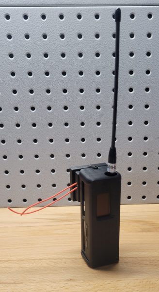
When you are done with this project, the two wires coming out are what you add to circuit you want to control, in place of a simple toggle switch. When the remote switch receives a command to close the circuit, the circuit will be closed for 5 seconds, and then re-opened.
Alternatively, you can build this as a normally closed circuit, and then this remote switch will open the circuit for 5 seconds.
This remote switch fully supported in the ChatterBox Communicator and Node firmware as of v1.0.3.
This is an advanced/experimental feature. Do not attempt unless you are willing to accept risk and know what you are doing.
3D Print Relay Enclosure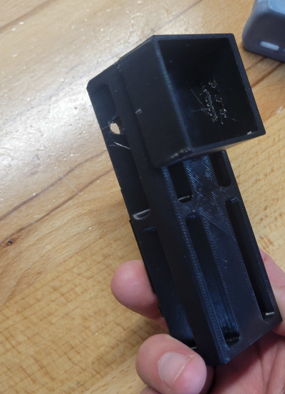 | This case is based on an original design from AlleyCat. I modified it to add a small enclosure for housing a relay module. STL Files Enclosure Back Enclosure Front Relay Cover Enclosure Buttons |
Gather Components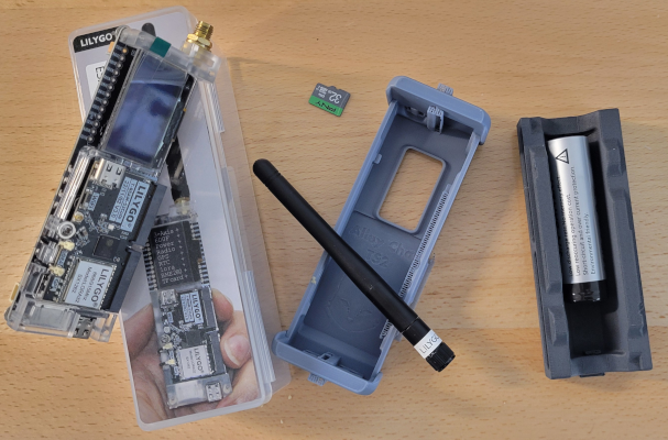 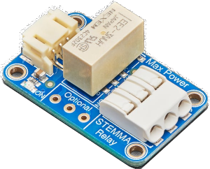 | In order to signal the relay, the ChatterBox node sends a HIGH signal to the pin. So, in theory, any relay switch that can be signaled with a HIGH could be used. Here, I use an Adafruit non-latching relay. The T-Beam has pins to support both 5V and 3.3V, but I have only personally used the 3.3V pin. Buy from Adafruit (unless you can find elsewhere): Adafruit Non-Latching Relay Rokland Links T-Beam Supreme Battery (18650) Amazon Buy Links T-Beam Supreme SD Card Battery (18650 flat) Heat Inset Nuts M3 Screws AliExpress Product Links: T-Beam Supreme SD Card Battery (18650 flat) Heat Inset Nuts M3 Screws |
Solder VCC/GND/Signal Wires to T-Beam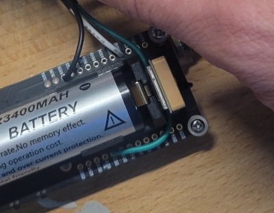 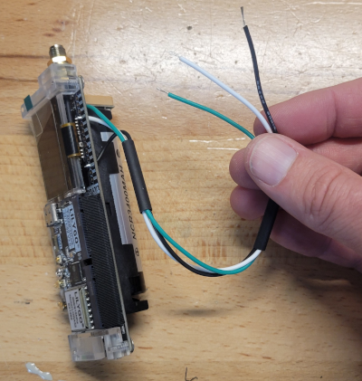 | I typically use white for voltage, black for ground, and green for signal. As shown here, you’d connect: Green -> Pin 46 White -> DC1 (3.3v 500mAh) Black -> GND |
Add Heat Inserts  | Using a heat gun and light pressure from a screwdriver, carefully press the inserts into the T-Beam back. |
Route Wires To the Relay Housing 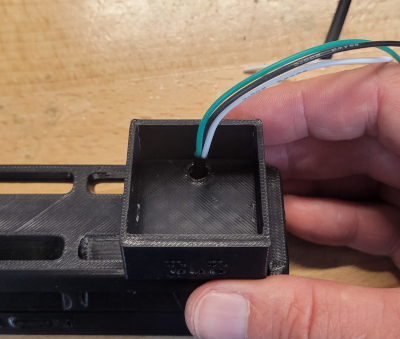 | Route all 3 wires through the back of the case into the housing where the relay will sit (the hollowed out square area). |
Connect VCC/GND/Signal to Relay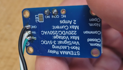 | You may choose to use a plug. I soldered the wires, but either way… Green -> Sig White -> Vin Black -> Gnd |
Connect the Circuit Wires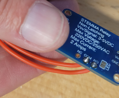 | Here is where you choose to connect Normal Open (NO), Normally Closed (NC), or both. I’m using normally open. This is pretty self-explanatory, but if you don’t know what those mean, I’m not going to explain it here (you should learn more about circuits before completing this project, or you could easily get injured or cause damage if you don’t know what you’re doing). |
Insert the Relay Module and Route Wires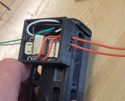 | Insert the relay module into the housing and route the circuit wires out, so you can connect them to your circuit |
Attach Relay Housing Cover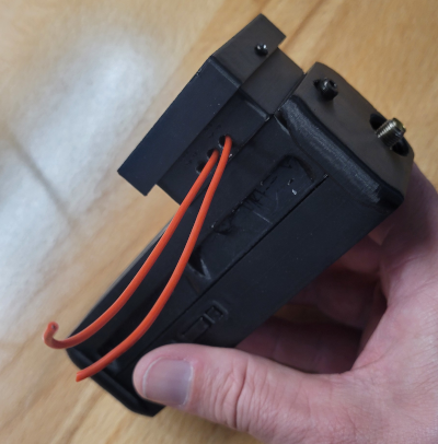 | |
| Complete “Node” Setup | The rest of the setup is essentially the same as a standard T-Beam Supreme node, starting with the insert SD card step. |
| Test your Remote Switch | Once your swich/node is onboarded, use any Communicator to test flipping the remote switch. The Node/Remote Switch * Power on your node/switch and wait for it to initialize. * Attach the switch wires to a simple circuit, such as a continuity tester that beeps or otherwise indicates whether a circuit is open or closed. Any Communicator * Enable “Experimental Features” in your communicator * Go to the Devices screen and select this switch * Open the commands menu, by touching the game controller button * Scroll to the Trigger Relay item, and choose it Within a couple of seconds, you should see the switch opened or closed for 5 seconds, depending on how you wired it. |