WARNING: Do not attempt unless you have a good understanding of electricity, wiring, and batteries. LiPo batteries can be dangerous and cause fires!
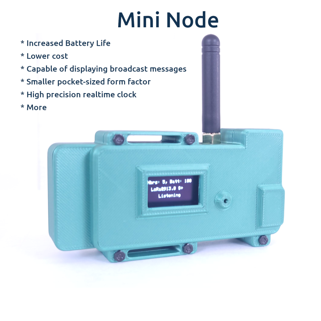
The Lilygo T3S3 makes a perfect low-power ChatterBox node. The T3S3 mesh node is easy to assemble, cheap, has a soldered SMA connector, and just enough display to let you know how its functioning or read short messages.
The T3S3 is what is used in the ChatterBox solar mesh node. ChatterBox mesh node firmware gives you the options to remotely enable/disable the OLED display, which also lowers power consumption.
Print Your Case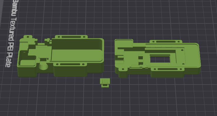 | 3D print the enclosure for your Mini Node. There are 3 parts to the enclosure, which you can download here. STL Format 3MF Format |
Gather Components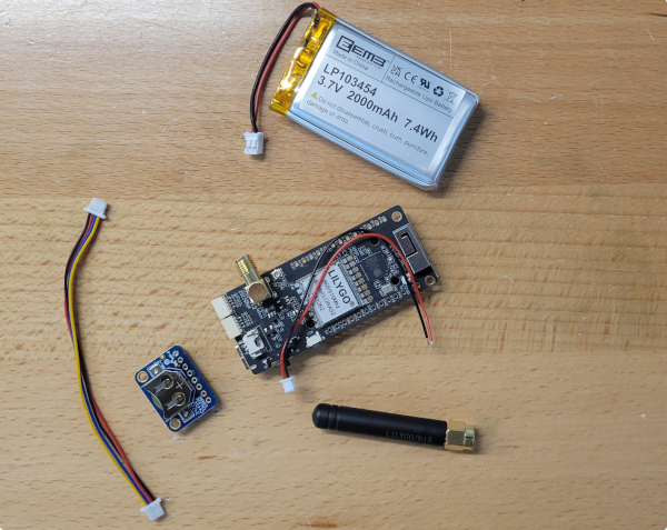 | Lilygo T3S3 – SX1262 Version The Stemma version of DS3231 requires no soldering, so you may prefer it. Adafruit DS3231 Stemma OR DS3231 2000 mAh LiPo Battery Qwiic Connector SD Card (optional, recommended) M2 Knurled Nuts M2 Bolts |
RTC – Stemma – Plug in RTC 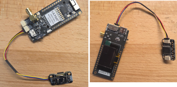 | If you’re using the Stemma verision of the RTC, simply plug it into the T3S3 as shown here. |
RTC – Non-Stemma: Solder Qwiic Connector to RTC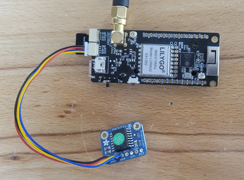 | On the DS3231, we only connect VIN, GND, SDA, and SCL. I connect it here using a Qwiic connector, for easy removal/replacement, as well as chaining together other I2C components later on. The Quiic connector is soldered as follows: Red : VIN Black: GND Yellow: SCL Blue: SDA Plug Qwiic Into T3S3. As far as PINS, the connections end up being: Pin 43 -> SCL Pin 44 -> SDA Although not shown, you can substitute a DFRobot 1103 GNSS/RTC module here, if you switch the DFR to I2C (instead of UART) and follow the same pin mappings as above for SDA/SCL connections. |
Add a Battery to the RTC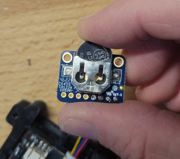 | The Adafruit RTC takes a CR1220 |
Press Nuts into Case Back and 2 PCB Holes 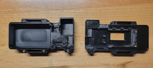 | There are inexpensive soldering tips for this, but you can also use a heat gun and screwdriver. |
Add All Components to Enclosure as Shown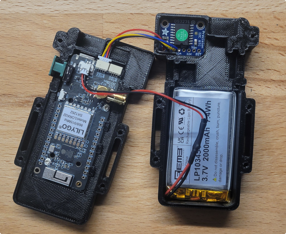 | Connect the battery and insert both the battery and RTC into the case back as shown. Be careful to make sure the polarity of the battery is correct for the T3S3. Markings on the T3S3 show +/- to help you get this right. The plug will not necessarily have the correct polarity or match the image shown. |
| Secure PBC to case front with M2 Screws | The 2 PCB holes on the T3S3 should line up with knurled nuts on the case front. Secure the T3S3 with one or two screws. |
| Close the case and attach Antenna | Use M2 screws to secure the case shut, and attach the antenna of your choice. |
Flash the Device | Visit one of the following sites to flash your device: chatters.io/flash offgridcomms.club/firmware/ meshcomms.club chatterbuilds.pages.dev |
| Power on and onboard | The new node should power up and go through a quick automatic setup cycle. This can take several seconds, after which it will reboot, and be in “Onboard Mode”, waiting for you to use your root device and onboard this new node into the your cluster. |