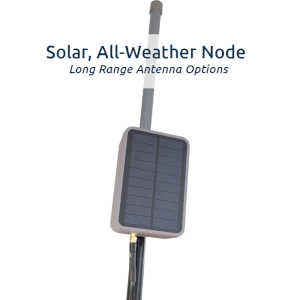
This ChatterBox outdoor solar mesh node uses an IP67 rated enclosure with integrated solar panel. The enclosure we use here is made by Rak. The hardware we will put inside is the Lilygo-based node.
You will need to solder a few connections and have some patience. There is not much room in the enclosure for all this, so it’s kind of like putting together a puzzle.
This has been recently redesigned with a lower power T3S3 node to make it through multiple days with little to no sun.
Download as PDF: Build Mesh Solar Node
Once it’s assembled, check out our solar mesh node quick start guide.
NOTE: These instructions are for ADVANCED hobbyists only and may contain mistakes. Attempt this at your own risk. Incorrectly assembling components like this can cause fires and other bad things. This may contain typos, parts you order can have the opposite polarity as shown here, so you need to understand electronics and what your are building, and not just blindly follow these instructions.
Gather Your Components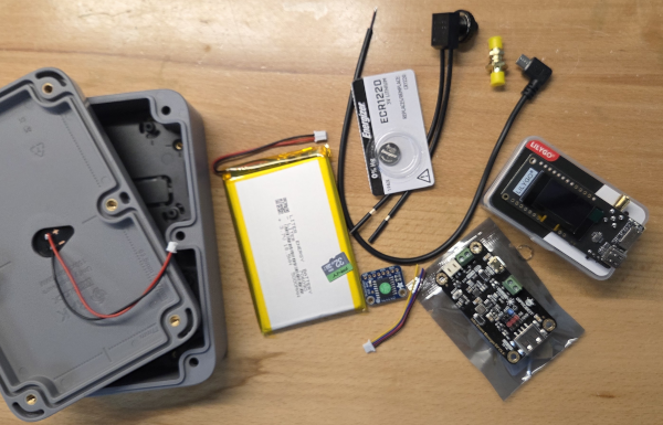 | In addition to the enclosure, you’ll want to check the available enclosure mounting options (at Rak). There are options for mounting vertically, sideways, etc. You can select whatever antenna makes sense for your application here. I typically use the shorter fiberglass omni antenna, which is linked to the right (and works great), but you can always experiment with different options. Rak Unify Enclosure Antenna SD Card DFRobot Solar Power Manager PH2.0 Pre-crimped cable kit Waterproof Latching On/Off Switch Marine Heat Shrink Tubing Wire Lilygo T3S3 sx1262 If the T3S3 / sx1262, you can substitute the T3S3 E-Paper 5000 mAh LiPo Battery SMA Male to Male 90 degree 12″ cable USB Micro Adapter Qwiic Cable Connectors The Stemma version of DS3231 requires no soldering, so you may prefer it. Adafruit DS3231 Stemma OR DS3231 Waterproof SMA Connector USB A male cable with bare ends Nylon Spacers Solder, Heat Gun, Soldering Iron |
RTC – Stemma – Plug in RTC 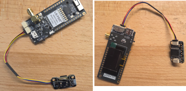 | If you’re using the Stemma verision of the RTC, simply plug it into the T3S3 as shown here. |
RTC – Non-Stemma: Solder Qwiic Cable to RTC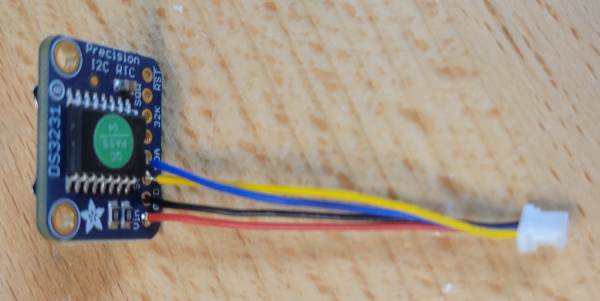 | The RTC will be connected to the T3S3 using a Qwiic cable, so we can easily swap it out any time. The connections shown here (assuming your qwiic cable is the same): Blue -> SDA Yellow -> SCL Black -> GND Red -> VIN |
RTC – Non-Stemma: Connect the RTC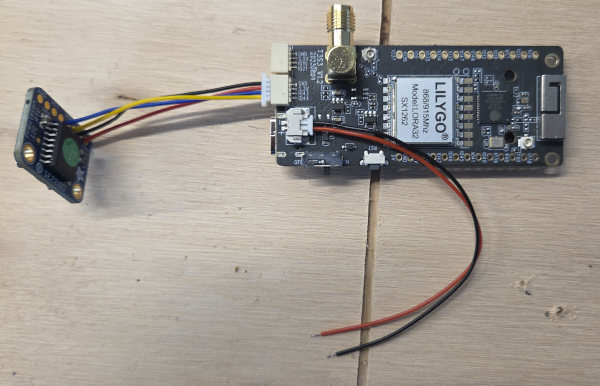 | Plug the Qwiic connector into the socket shown here (IO43/44). If you’re using the E-Paper T3S3, plug into its Qwiic connector (it only has one). Also install the RTC battery. |
Connect the On/Off Switch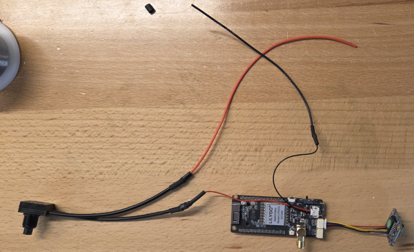 | Use the power plug that came with the T3S3, and plug that into the T3S3. Lengthen the ground wire by soldering a length of black wire to it. Solder one wire from the on/off switch to the T3S3’s red/vin wire, and extend the other on/off switch wire with a short length of red wire. |
Prepare the DFR Charge Controller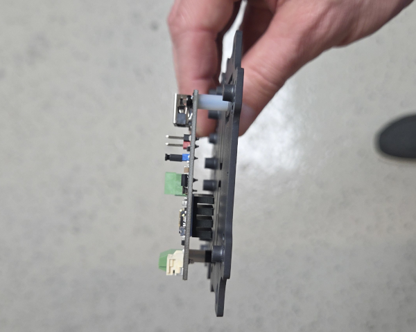 | Add the heat sink (included with DFR) to the charge controller. Mount the charge controller to the Rak’s base plate as shown, with spacers. |
Add the T3S3 to the Base Plate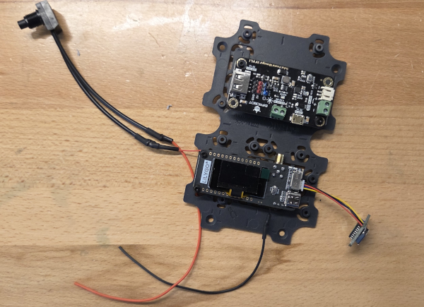 | Mount the T3S3 to the base plate as well, also with nylon spacers. Orient both boards as shown on the plate. |
Drill a hole for the On/Off Switch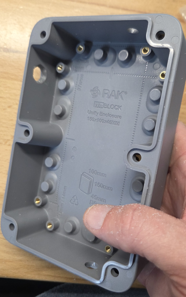 | A 3/8″ drill bit is the right size for the switch linked in the parts list. The inside portion of the hole does need to be a little larger than 3/8″, so you can either wiggle the drill around to widen the hole or use a dremel or hobby knife to enlarge the inner part of the hole. The On/Off switch should press into place as shown here, with no space. You could super glue this into place if you want, but I just screw the cap on to hold things in place. |
Install the Rak Cable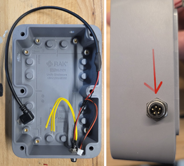 | Add the included Rak 4 pin cable to the enclosure as shown. Be aware of how you orient the pointed (internal) portion of the connector (see arrow), as you’ll need to orient your charge cable the same way, if you ever charge using USB instead of solar. Also solder the bare USB-micro 90 degree cable to either of the red/black wires from the Rak cable. Since we don’t use the yellow cables at this time, I trim them down enough to be well out of the way. |
Add the LiPo Battery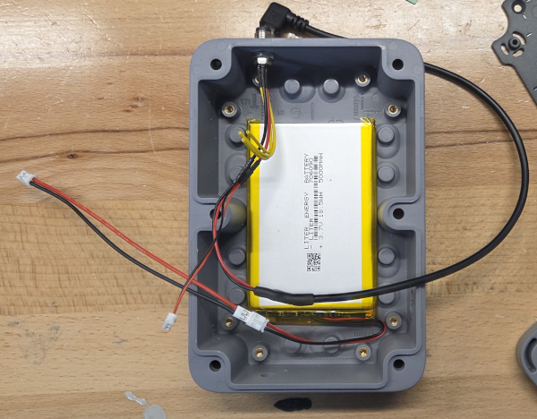 | Add the LiPo battery as shown. There should be room for it to easily fit in the space between flush with the back of the enclosure. Also create an extension cable for the battery, which will plug into the charge controller’s battery port. This is what I use the PH2.0 cable kit for. |
Install and Wire Everything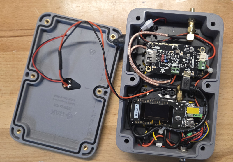 | This is several steps in one, because I didn’t separately capture images of the remaining steps. Install the base plate Orient it as shown Install the On/Off Switch Tighten it to the hole you drilled Antenna Connectors * Install the SMA connector * Connect the T3S3’s SMA connector to the enclosure’s SMA connector using the 90 male-to-male cable as shown * Install an antenna, even if it’s just a small temporary one to allow you to complete onboarding. Don’t run it without an antenna connected. On the DFR Charge Controller * Plug the battery into the battery port * Plug the T3S3/power switch Red wire into the DFR’s battery + port * Plug the T3S3 Black wire into the DFR’s battery – port * Plug the solar panels red/black wires to the DFR’s solar connection port. Notice I had to extend the panel’s wires. * Plug the USB micro connector into the DFR’s usb micro port Install a Blank Compatible SD Card See the compatible list. You can get by without an SD card if you want, but resetting the node would then require re-flashing. With an SD card, you just have to clear off the SD card to completely reset it. Create Charging Cable The Rak came with a 5 pin cable. Solder the USB A cable’s black/red wires to the Rak cable’s red/black wires. We don’t currently use the Rak cable’s yellow wires. |
Install the Node Firmware | Install the mesh node firmware by visiting the node flash page. You will want the T3S3 firmware, unless you’ve built this with an E-Paper node. If you have trouble, you may need to hold the T3S3’s boot button (tiny button on the front of it) while you reset it, then let up on the boot button – before flashing it. |
| Onboard the Node | I like to see the display of the node while it’s being onboarded, so I do this step before closing the enclosure. Get your root device (communicator) and onboard this new node. Sometimes it does take a couple of tries, and you might have to restart both devices, but once it’s done you should see the node listening and hopping frequencies (shown on display). You may have to temporarily attach an antenna here, just so the signal is good enough for onboarding. It’s not always necessary. Instructions for Onboarding a Node |
| Turn off The Display | Use a communicator’s command screen to disable the new node’s display, for longer battery life. You can re-enable the node’s screen any time, using the same screen. |
Close Rak Enclosure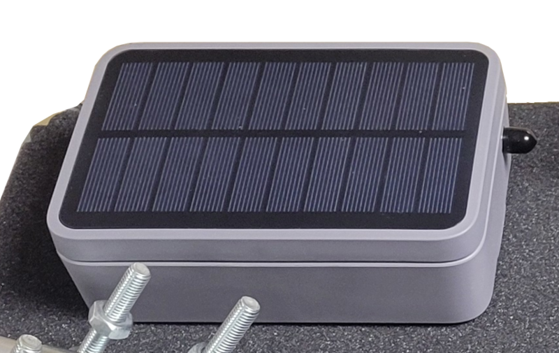 | Add the seal and bolt the enclosure shut. DONT FORGET TO ADD THE SEAL! |
| Add Mounting Brackets to Rak Enclosure | |
Mount Rak Enclosure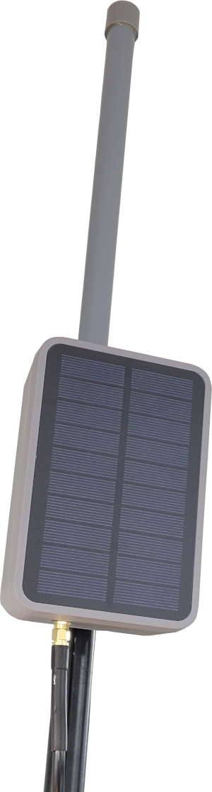 | Connect the antenna to the enclosure using cable included with the antenna. You may want to apply silicone around the connections, but that’s up to you. Mount the Rak encosure to the pole or whatever your application calls for. |
| Forget about it! See our solar node quick-start guide | If you have the solar panel facing a good direction, you should now have a functioning node that needs no maintenance. If the node completely drains the battery, due to lack of sunlight, whenever it does collect enough of a charge, it should automatically power back on and begin functioning as normal. If you live in a location that has long periods without decent sunlight, you may have to top off the charge sometimes. If you live in an area with frequent strong sun, you will likely never have to do that. In the worst case, you can power the node off for a while to let it charge from sunlight with the node not even checking the battery level (which does take current). |
| A note about GNSS | You do have the capability to remotely turn GNSS on and off from any communicator, using the button that looks like a game controller on the communicator’s devices screen. That might be a bad idea, as that is one way time is kept in sync. If you turn off GNSS, over time, the node’s clock may become out of sync with the rest of your cluster, which would make it “disappear” from connectivity. If that happes, you may simply need to restart the node to make it reappear. However, I would suggest simply leaving GNSS turned on. If you do leave GNSS running on the node, whenever the charge level falls below 20%, GNSS is automatically disabled until the charge level becomes higher than 50%. |