You can create a node that doubles as a mesh proximity sensor by slightly modifying a T-Beam supreme. You do not have to add a relay, but the instructions below cover adding both a mmWave radar and relay. The ChatterBox mesh node firmware automatically senses if you’ve added a proximity sensor to your node and cluster.
Warning : If you do not have a good understanding of electrical circuits, this is a dangerous project! Do not complete this project unless you thoroughly understand what’s going on here. This should be considered experimental and is for informational/educational purposes, and ALTWARE DEVELOPMENT LLC is not liable for any harm or injury caused by using the information here! Complete this project at your own risk.
Due to how packets are delivered via mesh, if your command is sent through mesh (and not direct), it is POSSIBLE your On/Off command could be delivered more than once as the firmware is currently written. Keep this in mind if you implement this or a similar project.
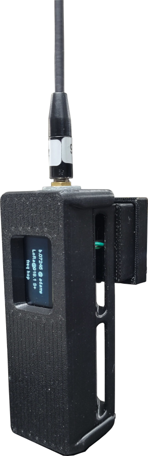
3D Print Relay Enclosure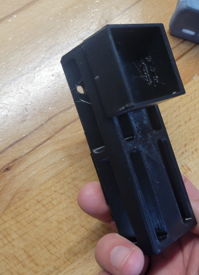 | This case is based on an original design from AlleyCat. I modified it to add a small enclosure for housing a relay module. STL Files Enclosure Back Enclosure Front Relay Cover Enclosure Buttons |
Gather Components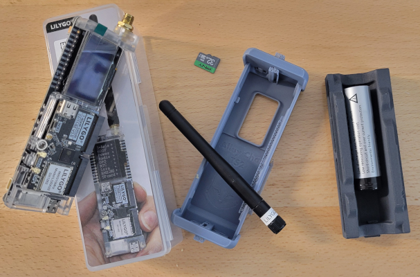 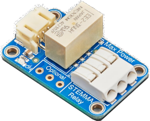 | In order to signal the relay, the ChatterBox node sends a HIGH signal to the pin. So, in theory, any relay switch that can be signaled with a HIGH could be used. Here, I use an Adafruit non-latching relay. The T-Beam has pins to support both 5V and 3.3V, but I have only personally used the 3.3V pin. Buy from Adafruit (unless you can find elsewhere): Adafruit Non-Latching Relay Rokland Link T-Beam Supreme Battery (18650) Amazon Buy Links T-Beam Supreme DFRobot mmWave Radar SD Card Battery (18650 flat) Heat Inset Nuts M3 Screws AliExpress Product Links: T-Beam Supreme DFRobot mmWave Radar SD Card Battery (18650 flat) Heat Inset Nuts M3 Screws |
Solder VCC/GND/Signal Wires to T-Beam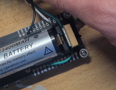 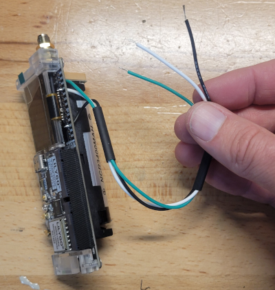 | I typically use white for voltage, black for ground, and green for signal. As shown here, you’d connect: Green -> Pin 46 White -> DC1 (3.3v 500mAh) Black -> GND |
Prepare DFRobot Wires for Soldering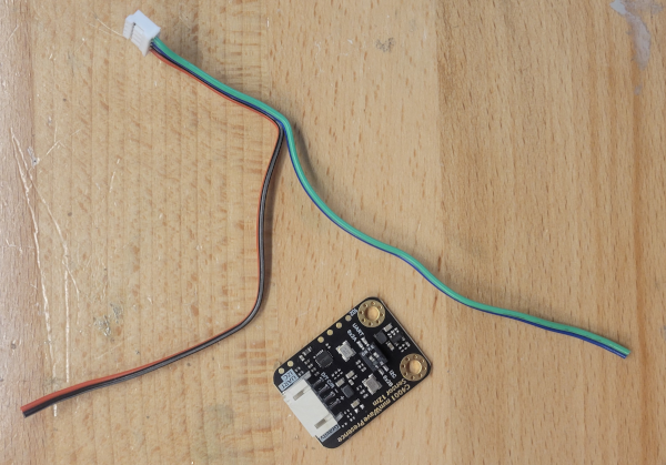 | We will be using the white plug end of the DFRobot-included wires, but need to cut the black dupont adapters from the other end. You’ll also want to separate the blue/green wires from the red/black, as shown in the image. NOTE: Route the DFRobot blue/green wires through the relay housing (as shown a few steps down) before soldering. The DFRobot white plug will be sitting in the relay housing. |
Solder DFRobot SDA/SCL Wires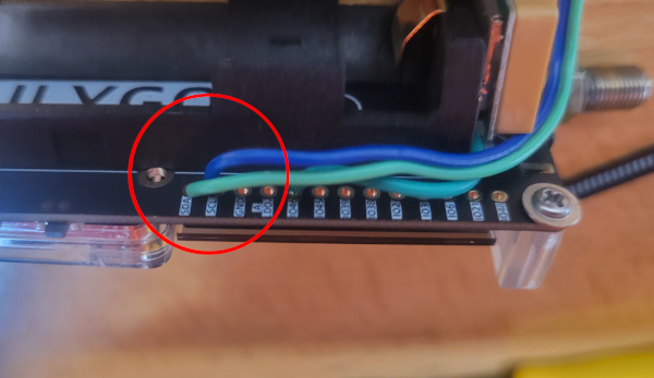 | In the wires provided with the DFRobot sensor: Green (Data) goes to SDA Blue (Clock) goes to SCL |
Add Heat Inserts  | Using a heat gun and light pressure from a screwdriver, carefully press the inserts into the T-Beam back. |
Route Wires To the Relay Housing 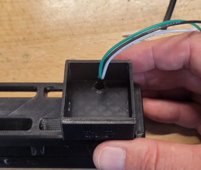 | In addition to the 2 DFRobot wires that have been routed through the relay housing, route all relay wires through the back of the case into the housing where the relay will sit (the hollowed out square area). The image to the left only shows 3 wires, you should have 5 wires routed through here, and be left with the DFRobot’s red/black wires waiting to be connected to something. |
Connect VCC/GND/Signal to Relay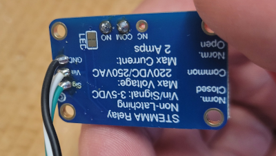 | You may choose to use a plug. I soldered the wires, but either way… Green -> Sig White -> Vin Black -> Gnd |
Connect the Circuit Wires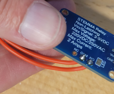 | Here is where you choose to connect Normal Open (NO), Normally Closed (NC), or both. I’m using normally open. This is pretty self-explanatory, but if you don’t know what those mean, I’m not going to explain it here (you should learn more about circuits before completing this project, or you could easily get injured or cause damage if you don’t know what you’re doing). |
Insert the Relay Module and Route Wires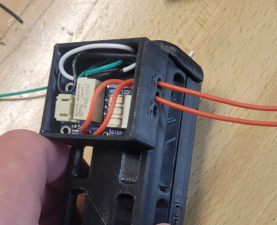 | Insert the relay module into the housing and route the circuit wires out, so you can connect them to your circuit |
Set DFR to use I2C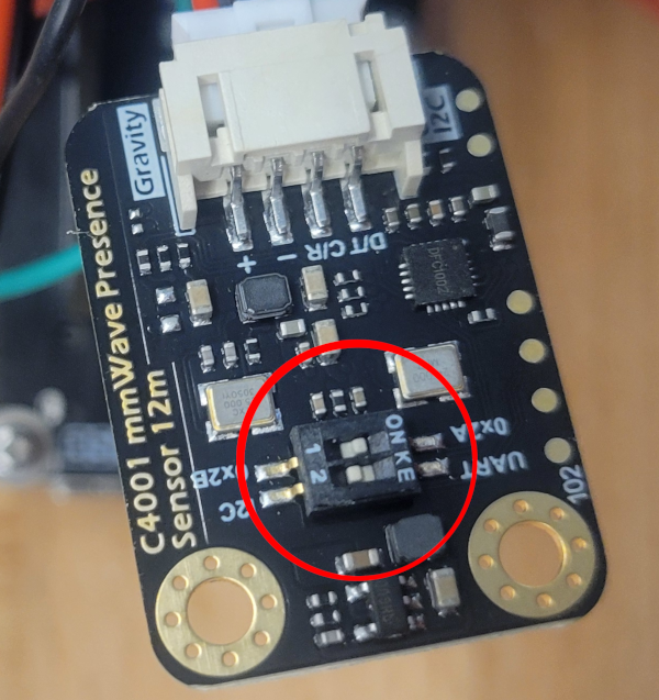 | The DFRobot sensor has two switches. 1) Controls the device’s I2C address. Leave it at 0x2A 2) Controls UART vs I2C. Switch this to I2C |
Connect the DFRobot Power/Ground to the Relay’s Power/Ground.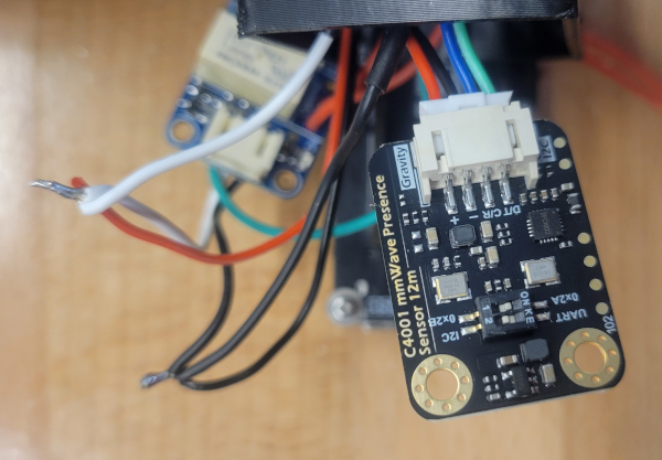 | Connect the DFR’s 3v/Gnd wires as shown to the left. You will need to cut the relay’s white and black wires, to splice them back together along with the DFR’s +/Gnd. You may want to do the wiring differently than what I’ve done here, but essentially both the DFRobot sensor and relay will be powered from the same connections on the T-Beam. I simply twisted and soldered the wires as shown, and then slid/shrunk a heat shrink insulator over each set of wires. |
Tuck the Components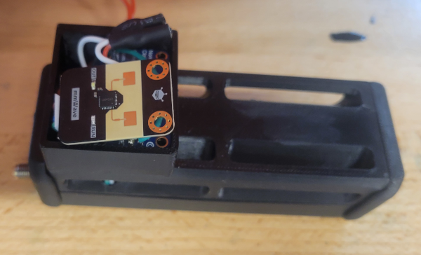 | Tuck the Relay and DFRobot sensor into the relay housing as shown. It will be a tight fit. |
Attach Relay Housing Cover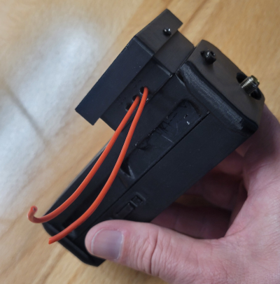 | |
| Complete “Node” Setup | The rest of the setup is essentially the same as a standard T-Beam Supreme node, starting with the insert SD card step. |
Test your Remote Switch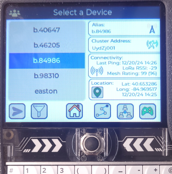 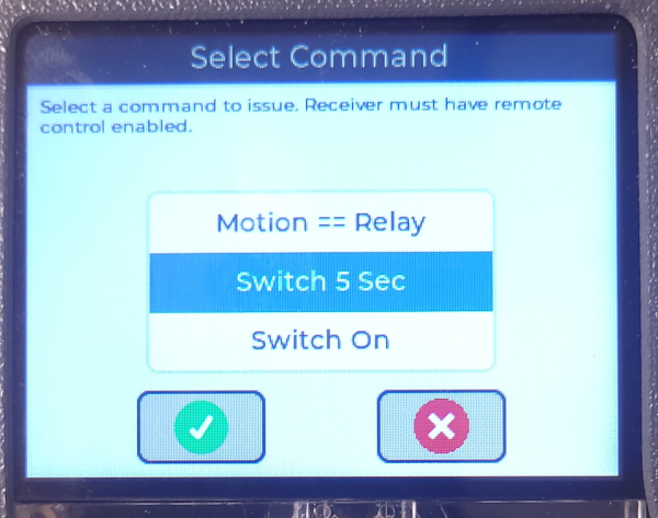 | Once your swich/node is onboarded, use any Communicator to test flipping the remote switch. The Node/Remote Switch * Power on your node/switch and wait for it to initialize. * Attach the switch wires to a simple circuit, such as a continuity tester that beeps or otherwise indicates whether a circuit is open or closed. Any Communicator Within a few minutes of being onboarded to your cluster, communicators should start to become aware of this new node, and should show it (on the devices screen) as a motion sensor. * Go to the Devices screen and select this device * Open the commands menu, by touching the game controller button * Scroll to the Switch 5 Sec item, and choose it Within a couple of seconds, you should see the switch opened or closed for 5 seconds, depending on how you wired it. You can also use the Last Motion command to test whether the sensor is working. If you are anywhere near the node, you should get a response of a time near the current time. |